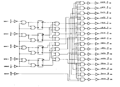
4 to 16 decoder using 2 to 4 decoder verilog code 2 to 4 decoder circuit diagram 4 to 16 decoder using 2 to 4 decoder verilog code 4 to 16 decoder circuit with 2 bit decoder diagram
Circuit Diagram Of 4 To 16 Decoder - Circuit Diagram
Decoder circuit diagram using gates 4 16 decoder circuit diagram Arten von encodern und decodern mit wahrheitstabellen und anwendungen
Digital circuits
2 to 4 decoder circuit diagramDecoders decoder using 16 build two only logic circuit gates input use not 4 to 16 decoder4 bit decoder circuit diagram.
4 to 16 decoder circuit diagram4 to 16 decoder circuit diagram 4 to 16 decoder circuit diagramDigital logic.

4 16 decoder circuit diagram
Decoder 16 circuit using diagram designingHow to design a 4 to 16 decoder using 3 to 8 decoder 4 to 16 decoder circuit diagram3. draw the circuit for a 4-to-16 decoder using only.
Solved design a 4-to-16 decoder using 2-to-4 decoders. theDecoder logic circuit diagram and operation 4 to 16 decoder circuit diagramCircuit diagram of 2 4 decoder.

4 to 16 decoder circuit diagram
Solved: chapter 5 problem 52e solution3 to 8 decoder logic diagram What is a decoder in logic circuitsVerilog code for 4 to 16 decoder using 3 to 8 decoder.
Decoder decoders vhdl implement 2x4 4x16 verilog rtl 52e solvedDecoder 2 to 4 circuit 4 to 16 decoder circuit diagramCircuit diagram of 4 to 16 decoder.

4 to 16 decoder circuit diagram
4 to 16 decoder circuit diagramCircuit diagram of 4 to 16 decoder Solved draw the circuit for a 4-to-16 decoder using only 2.
.


